Created By Joshua Bryant
Configuring & optimizing the printer
The first and most important steps to a successful print is making sure your printer is aligned and your settings are optimize to the material being used.
- Align your print bed and/or level your Z-Axis plane
- Calibrate your print head (this varies per printer manufacturer)
- Know your material! - I suggest printing a good calibration set to do this (one that I use can be found HERE on Thingiverse) *NOTE: You will need calipers
- + Shrinkage compensation - You will need to understand your materials shrinkage rates so that you can model to accommodate them.
Example: If you have a 3mm bolt for a printed hole you would want to oversize your modeled hole so that when the part cooled it would measure 3mm after shrinking.

- + Bridging ranges - Some materials can bridge longer distances than others, so its good to know ranges for understanding your model limitations. Bridging quality and distance is greatly affected by the extrusion temperature and print speed settings.
- + Size & Shape - Each material will have a different quality rating, so for the best results always measure by hand in multiple spots along the filament. Make sure you apply the average of your findings to the filament diameter variable. *NOTE: If your filament is a bit oval simply average the major & minor diameters; ie: If it measures 1.77 & 1.75 then use 1.76 as the diameter.
Example: Below is a measurement from a small segment of Flex EcoPLA, this material tends to run on the bigger side of the 1.75mm standard (short review).

- + Speed, Flow, & Cooling - These variables are crucial for tuning to each material. There are many combinations you can make with these variables, finding the sweet spot is critical. For me a good configuration will give me quick printing speeds, minimal drooping on bridges, smooth walls, & fully filled floors.
- Air Temperature Management - Another key component for a good print is maintaining a constant air temperature with no air drafts. Without good air control you can experience lifting and curling on your print (print-bed temperature also effects this). Air control can be accomplished in a few different ways.
- + Covering Printer - This is the method I use. Some people cover their printers with a cardboard box, but I find this method insulates the heat too much and I don't like that it removes visibility. So for my enclosure I simply used thin painters plastic and draped it over the printer like a tent. It keeps air temperature constant and prevents any air drafts.
- + Printing Room - For those who have the space, time, & money you can construct a printing room to isolate your air temperature.
*Note: With either method make sure to separate your filament from the enclosure. Although you want you air around the part to be constant and warm, this can be hindering to the filament. Warm filament (especially flexible types) will begin to warp and become less ridged under heat, this can cause extruder jamming. - Model for manufacturing - When designing something always take its 'printability' factor into consideration. An ideal model should be able to be printed without support using as little material as possible to hold design intent. This is not always possible, but the closer you stick to an ideal print the easier & more cost effective it will be to make.
A better design for a better print
The major factor for a good and accurate print is to have your models designed for printing. As discussed above, the design of your model will have a direct correlation with your material's abilities.
- The base - The bottom of your model needs to have enough surface area to keep the model stuck to the print bed. For some materials this isn't an issue to be concerned about, but for others(like Flex EcoPLA) you may have to accommodate. For materials that don't like to stick you can print on a raft or use the skirt settings to help adhesion. The alternative method that I use myself is to model in a custom skirt(one layer thick) to help keep the model adhered.
Example: This is a rubber boot made for a motor cycle transmission cover. As you can see I modeled on a custom floor that can be easily trimmed away to help keep the part attached throughout the printing process.

As you can see below, the Flex EcoPLA wanted to curl so bad it started pulling up the tape.

*Personal Tip: I like to coat my painters tape with an Elmers glue stick then pre-heat the bed on 60C for 3min to get it good and tacky. This is one of my most useful tricks for keeping the part good and tacked to the tape.

[Now I just have to figure out how to keep the tape tacked to the bed at these higher temps]
[Using a plastic putty knife I was able to firmly seal the tape to the bed; Success! No lifting]
- Overhangs - When printing overhangs make sure to stay within your bridging limitations. There are several ways to enhance your overhang quality.

- + Add rounds or chamfers to bottom of an overhang to reduce the bridging distance

- + Add cross-section supports

- + Modify your settings - Adjust the print settings; decreasing extrusion temperature, increasing cooling, & raising the print speed. This will allow the strand to setup a bit quicker reducing the drooping effect on the overhang.
- Thin objects - When printing small pegs or posts add rounds or chamfers to the bottom edges. This will add a lot of strength to the design and keep your peg or post from just snapping off.

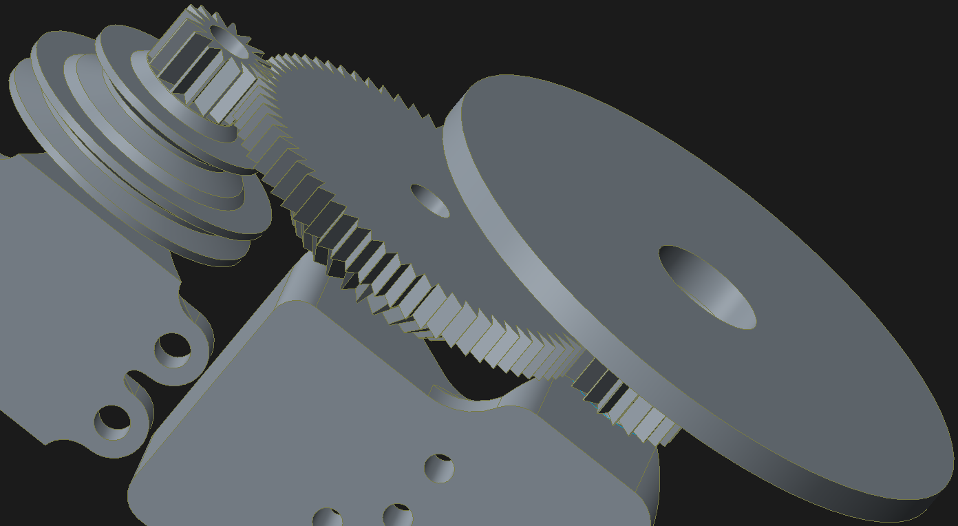
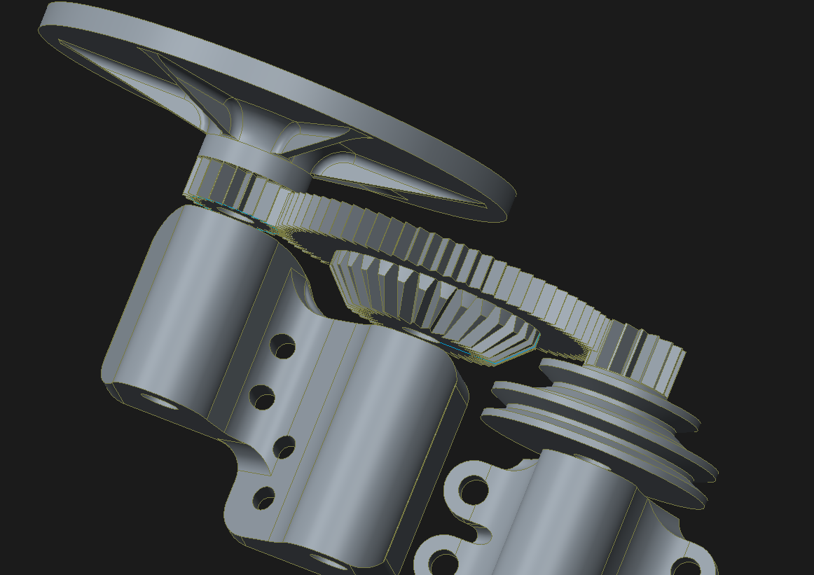
- Gears & Sprockets- Printing gears is one of the tougher objects to print because a lot of problems can occur in the design process. Whether it be a lack of teeth strength or poor mating between gears, many woes can arise. Printing a successful gear requires a little more engineering & involvement then most prints, but once you figure it out you can create some really cool creations (see rotary powered disk sander). Below are some key factors to take into consideration when creating gear components.
- + Accuracy - Printing gears requires great accuracy. The diameter needs to be just as accurate as the teeth's depth, width, & pitch; otherwise you will get a bad interconnection between gears. If the connection is too tight it can cause unnecessary resistance(and heat) or if there is too much of a gap it will lead to the gears striping out.
Example: The gear I printed below needed a +/-0.1mm tolerance to function properly as a helicopter gear replacement. As you can see, I had to print many iterations to get it just perfect.

*TIP: A good trick to save material is to print just the first 10 layers of the gear to test the fit of the teeth before printing the full gear.

- + Strength - Designing and printing a strong gear is just as important as the gear's size accuracy. To improve a gear's strength certain print settings must be adjusted. In your slicing software look for the 'wall thickness' variable and change this value to 1/2 the tooth's greatest width. This will ensure that the teeth of the gear are solid & strong, you don't want any infill to occur in the teeth of the gear. This can be checked by reviewing the pathing carefully within your slicing software.
Example: Below is an image depicting the ideal path you want to see in your teeth.

- ++ Another way to increase a gears strength is to thicken the gear's width, thus giving more surface area for the teeth to grab on to.
Example: For the sanding tool I created, I designed the gears wide and thick to handle the heavy duty application.

- + Heat Management - Like most all moving parts there is going to be heat generated. This is our greatest enemy when it comes to working with 'plastic' gears. Not all gear systems will need heat management, like actuating gears for levers and channels. For all other gears & sprockets that are constantly turning heat will become a factor. Below are some tips for keeping the heat generation to a minimum.
- ++ Add a bearing to the design - Roller skate bearings are a cheap and effective tool when building gears. Simply design an inset for the bearing to fit into.

- ++ Create a bearing - For those pure DIY projects you can also make a bearing for the gear. Using aluminum or some other smooth strong material you can design your own bearing.
Example: In the rotary sander project I used the hollow shaft of an arrow to act as a simple bearing between the bolt shaft and the printed hole.

Overview
As you can see 3D printing can be a great hobby and is a skill that simply just takes some practice to better at. You will find 3D printing really opens up some fun adventures in your life and can even save you some good money as you get better at designing. Below are some examples of things I've built & fixed to save me money.
- Crashed my $200 helicopter; Fixed it with 3D printed parts.


- Hard to find rubber transmission cover for a motor cycle; Cheapest I found if for was $70, printed it for $15 (*note: this was a two piece assembly)

- Old XMOD car was always chewing up batteries; Printed a new body and added a LiPo battery to power it for over 6hrs non-stop. It drives better then ever and even has LED headlights now.
- GoPro Mounts and Accessories; Retail $20-$50, I print for $5-$10
- Chip Clips
- Fasteners
- Stackable Storage
- Tent bracket; My grandfather's hunting blind broke a small plastic bracket that held the coupler together, he called the company and they said he'd have to by the whole coupler assembly for $49.99 +Shipping. I printed the bracket for less then $2 and repaired the coupler in less than 20min.
- Spools, holders, & wraps for wire, filament, hose, tubing, rope, cord, & meshing.
- Pegboard accessories; Dispensers, brackets, and other tool holders

And so much more, its all up to imagination and ingenuity to drive the next creation :-)
Donate 25¢ to help me keep creating